
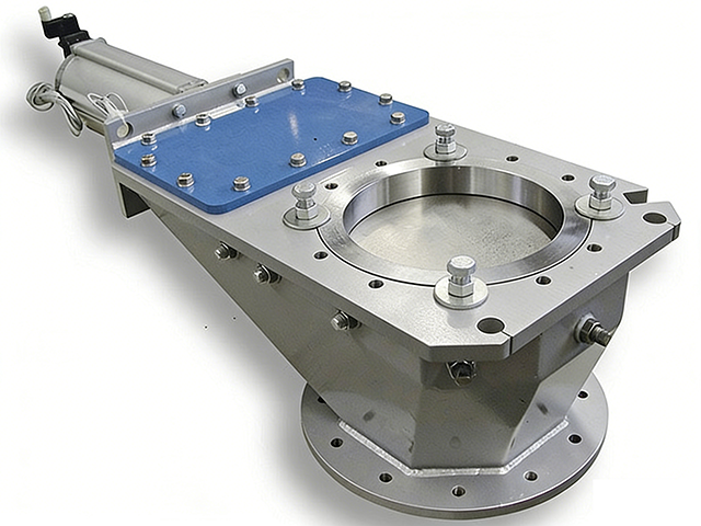
Coal Mill Isolation Door
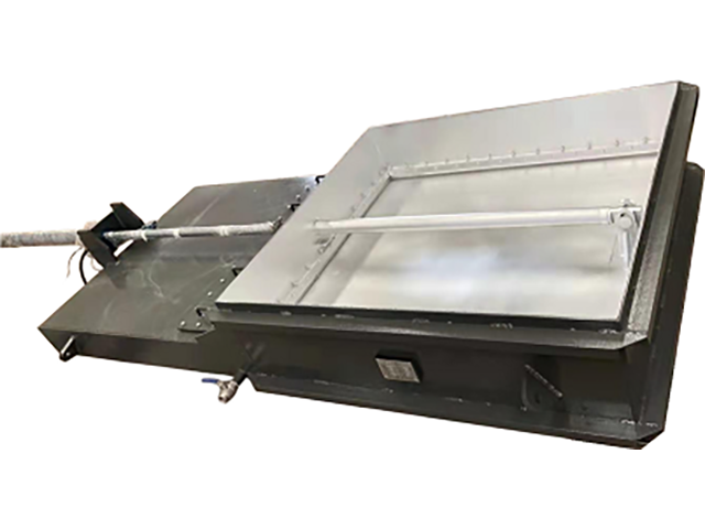
The coal mill isolation gate, also known as the coal mill slide gate (or coal mill shut-off gate), is…
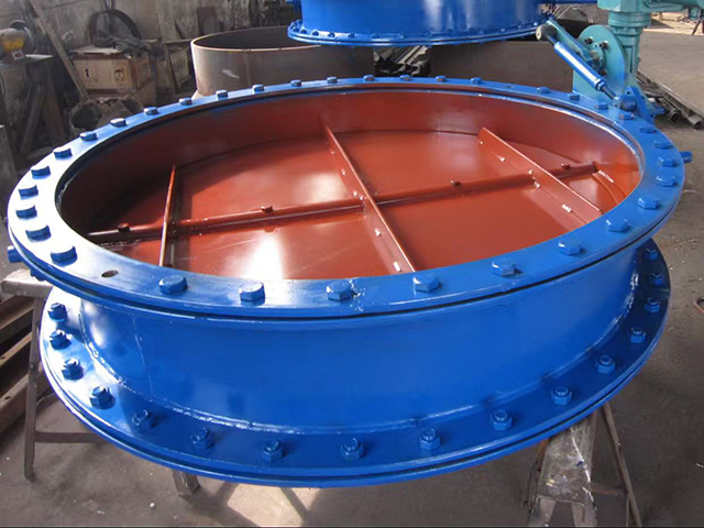
A high-temperature damper, also known as a Flue gas damper valve or high-temperature resistant damper, is a critical piece of equipment installed in high-temperature flue gas duct systems to shut off, connect

A high-temperature damper, also known as a Flue gas damper valve or high-temperature resistant damper, is a critical piece of equipment installed in high-temperature flue gas duct systems to shut off, connect, isolate, or regulate the flow of process media.
Its primary functions include system isolation, sealing, and flow control. High-temperature dampers are widely used in boilers, industrial furnaces, kilns, flue gas treatment systems such as flue gas desulfurization (FGD) and denitrification systems, as well as waste heat recovery systems in the power generation, metallurgy, chemical, building materials, and other industrial sectors.
This product is specifically designed for demanding operating conditions involving high temperatures, high dust concentrations, and corrosive media. It offers excellent sealing performance, high-temperature resistance, and structural stability, ensuring long-term reliable operation in harsh industrial environments.
The high-temperature damper is designed and manufactured with reference to applicable industrial standards and technical specifications, including:
GB/T 1184-1996 — Geometrical Tolerances: Tolerances of Form and Position
JB/T 8692-2013 — Technical Specifications for Air, Flue Gas, and Pulverized Coal Pipelines
DL/T 5072-2007 — Design Code for Thermal Insulation and Painting of Fossil Fuel Power Plants
Relevant industry-specific safety and technical standards
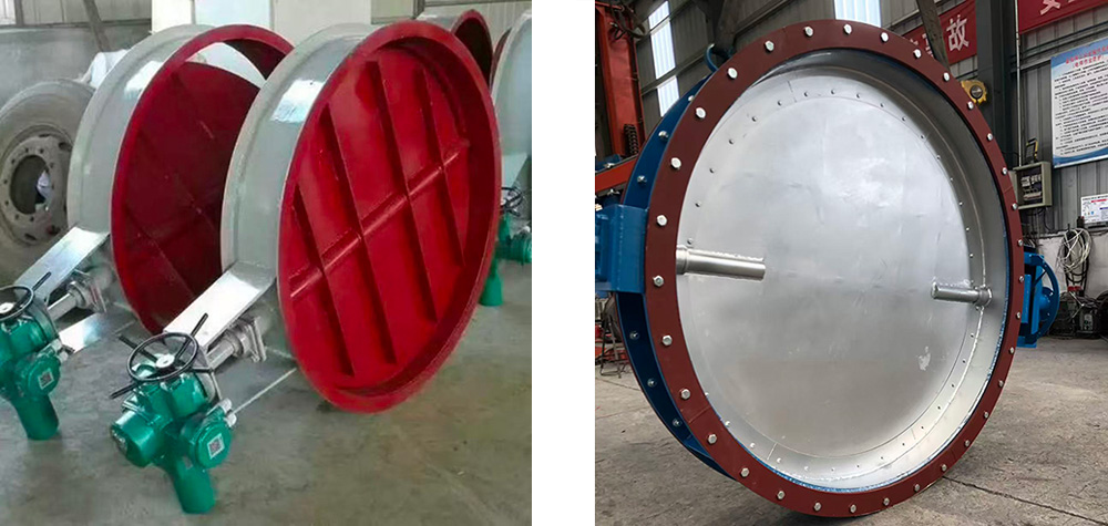
The high-temperature damper mainly consists of the following components:
The damper frame is fabricated from high-quality steel plates, such as Q235B or higher-grade heat-resistant steel. The robust welded structure provides sufficient strength and rigidity to withstand pipeline loads, thermal stress, and demanding operating conditions.
The damper blades are the core components of the equipment and are commonly designed in single-shaft, double-shaft, or multi-shaft configurations.
The blades are manufactured from heat-resistant stainless steel selected according to the operating temperature and corrosive characteristics of the medium. Common materials include 304 stainless steel, 316 stainless steel, and 310S stainless steel, providing excellent resistance to high-temperature deformation and corrosion.
The rotating shafts are manufactured from high-strength alloy steel. The bearings are typically high-temperature self-lubricating bearings or graphite bearings to ensure smooth and reliable operation without sticking or jamming under high-temperature conditions.
The sealing system generally includes the following components:
Flexible sealing elements are installed between the damper blades and the frame. These may include stainless steel sealing plates combined with graphite braided packing to ensure close contact and effective sealing when the damper is closed.
Stuffing box seals or labyrinth sealing structures are used to effectively prevent process media from leaking through the shaft openings.
For applications requiring extremely high sealing performance, a zero-leakage design can be provided. By introducing sealing air, an air barrier is formed on both sides of the damper blades to achieve complete isolation of the process medium.
The damper can be equipped with different drive systems according to application requirements, including:
Electric actuators
Pneumatic actuators
Manual worm gear mechanisms
The actuator can be equipped with torque protection and limit switches and can be integrated into a central control system for remote and automated operation.
The linkage mechanism synchronizes the movement of multiple damper blades, ensuring that all blades open and close simultaneously and operate smoothly.
The drive system transmits motion through the linkage mechanism, causing all damper blades to rotate synchronously.
When the damper is fully open, the blades rotate to a position parallel to the direction of media flow. This provides the maximum flow area and minimizes flow resistance and pressure loss.
When the damper is closed, the blades rotate to a position perpendicular to the direction of media flow and tightly engage with the sealing system, effectively shutting off the flow passage.
For regulating or modulating dampers, the opening angle of the blades can be precisely controlled to regulate the flow rate of the medium. Depending on the design requirements, linear or equal-percentage flow control characteristics can be achieved.
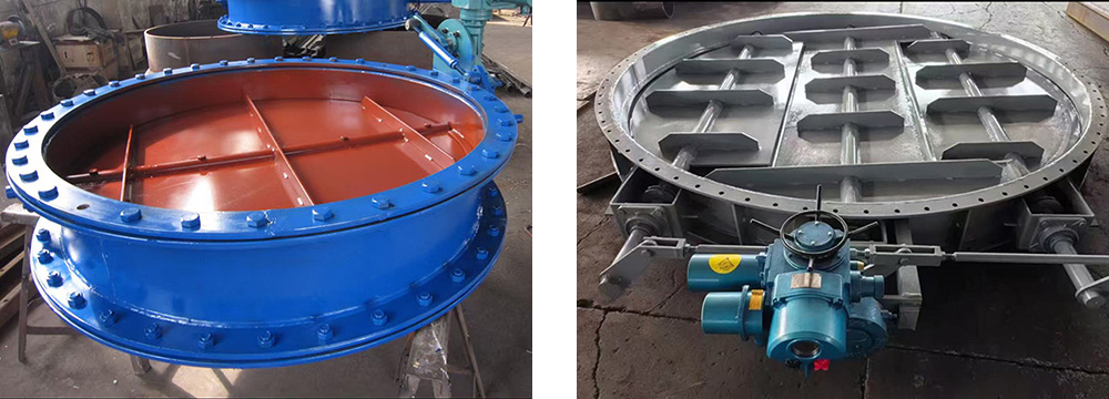
Key components are manufactured from heat-resistant steel and high-temperature-resistant materials. Depending on material selection and operating conditions, the damper can operate reliably for extended periods at temperatures ranging from approximately 350°C to 850°C, or even higher for specially designed applications.
The damper adopts a multi-level and comprehensive sealing system to minimize leakage. Under normal operating conditions, the leakage rate can typically be controlled to ≤1%, depending on the design and application requirements.
Specially designed zero-leakage dampers can achieve extremely high sealing performance through the use of sealing air.
The optimized structural design and the use of high-performance bearings significantly reduce the torque required for opening and closing. This ensures smooth operation, stable performance, and lower energy consumption.
The robust damper structure, thermal deformation-resistant blade design, and wear-resistant sealing materials ensure reliable operation and a long service life under harsh industrial conditions.
The damper supports electric, pneumatic, and manual operation. Position feedback signals can also be integrated to facilitate remote monitoring and automated control.
Many bearings and sealing components are designed to be replaceable. Maintenance can often be performed without completely dismantling the damper from the pipeline, helping reduce maintenance time and operating costs.
| Item | Parameter / Description |
Nominal Diameter (DN) | 200 mm–5000 mm (or customized as required) |
Design Temperature | 350°C, 450°C, 600°C, 850°C (or higher, customized) |
Design Pressure | ±8 kPa to ±10 kPa (or customized according to operating conditions) |
Main Materials | Damper frame: Q235B carbon steel; Blades and shafts: 304 / 316 / 310S stainless steel, etc. |
Leakage Rate | ≤1% (standard type); Near-zero leakage (seal air type) |
Actuation Method | Electric, pneumatic, or manual |
Power Supply / Air Supply | Electric: AC 380V / 50Hz; Pneumatic: 0.4–0.6 MPa clean compressed air |
Connection Type | Flanged connection (RF or RJ) or welded connection |
Surface Treatment | High-temperature corrosion-resistant coating (selected according to the temperature rating) |
To ensure proper damper selection and design, users should provide the following key operating parameters:
Duct dimensions, including diameter or width × height and wall thickness
Process medium
Operating temperature
Operating pressure, including positive or negative pressure
Required leakage rate or sealing performance
Drive method and control requirements
On-off or modulating operation requirements
Connection method with the pipeline or duct system
Special operating conditions, such as high dust concentration or strong corrosion
Providing accurate operating data helps ensure that the high-temperature damper is properly designed for long-term reliable service.
Before installation, confirm that the damper model and specifications are correct. Check the equipment for transportation damage, remove any foreign objects inside the damper, and ensure that all rotating components operate smoothly.
Use designated lifting lugs when lifting the damper to prevent impact or structural damage. Position the damper accurately in the duct system and ensure that the damper flange is properly aligned with the pipeline flange.
For welded connections, intermittent and symmetrical welding methods should be used where appropriate to minimize thermal deformation of the damper body.
For flanged connections, high-temperature-resistant gaskets should be used, and bolts should be tightened evenly in a diagonal sequence.
Before installation, carefully check the flow direction markings on the damper body and ensure that the equipment is installed in the correct orientation.
Install and connect the actuator according to the actuator manufacturer's instructions. After installation, manually test the fully open and fully closed positions and properly adjust the limit switches.
Before initial operation, manually operate the damper several times to confirm that there is no sticking, abnormal resistance, or mechanical interference.
During automatic operation, regularly monitor the operating condition of the actuator and verify position feedback signals.
The following inspections should be carried out regularly:
Check whether external fasteners are loose.
Inspect the sealing system and repair any leakage promptly.
For sealing-air dampers, ensure that the sealing air supply remains stable and clean.
Check the operating condition of the actuator and linkage mechanism.
Depending on operating conditions, periodic maintenance should generally include the following:
Every 6–12 months, inspect the bearing condition and lubrication system. Add or replace high-temperature lubricant when necessary.
Inspect the condition and wear of blade sealing elements and replace severely worn components in a timely manner.
Perform routine inspection and maintenance of electric, pneumatic, or manual drive systems.
Check the synchronization and operating condition of multi-blade linkage mechanisms.
With its precision-engineered structure, reliable material selection, and advanced manufacturing technology, the high-temperature flue gas damper is a critical component for ensuring the safe, efficient, and stable operation of high-temperature flue gas systems.
Its excellent high-temperature resistance, sealing performance, structural strength, and flexible control options make it suitable for demanding applications in power generation, metallurgy, chemical processing, building materials, industrial boilers, furnaces, flue gas treatment systems, and waste heat recovery systems.
Proper product selection, standardized installation, correct operation, and regular maintenance are essential for achieving optimal performance and extending the service life of the high-temperature damper.
The coal mill isolation gate, also known as the coal mill slide gate (or coal mill shut-off gate), is…
The Hydraulic slide gate valve, also known as a hydraulic slide valve, hydraulic gate valve…
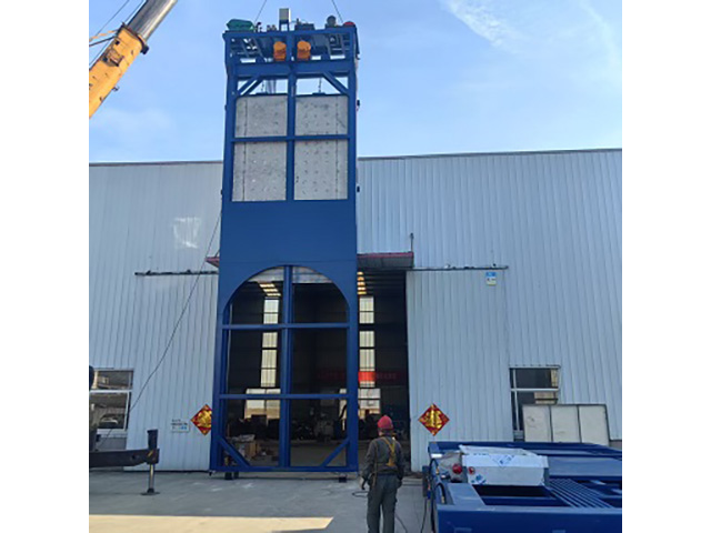
The implementation of a coke oven flue gas desulfurization project requires extracting flue gas from the…
FAQ
We manufacture power plant dampers (flue gas, desulfurization, high-temperature baffle doors), slide gate valves, blind flange valves, rotary film and sponge iron deaerators, venting silencers, automatic dosing devices, steam-water sampling devices and sampling coolers, coal powder samplers, condensate recovery units, coarse and fine powder separators, and plate / shell-and-tube heat exchangers.
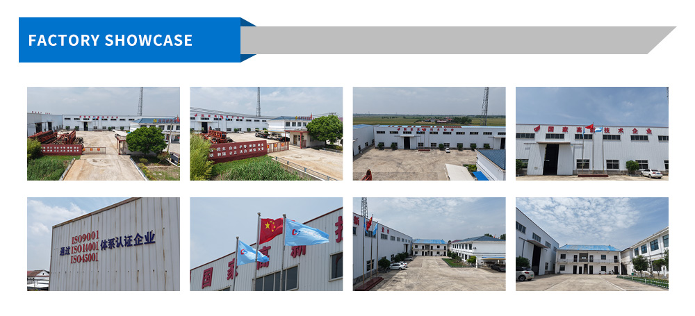
We are certified to ISO 9001:2015 (quality), ISO 14001:2015 (environmental) and ISO 45001:2018 (occupational health and safety) management systems. We are also a qualified supplier of Sinopec, PetroChina, China Guodian Corporation, China Datang Corporation, CNOOC and Aluminum Corporation of China Limited.
Yes — most of our business is retrofit supply. Send us the duct cross-section, design temperature and media, or drawings, templates and photos of the existing installation. Our engineers will dimension the unit, its flange drilling and the actuator interface to bolt directly into your plant.
Louver-type double-layer dampers with sealing air achieve a leakage rate below 0.5%; fully sealed slide gates and coal mill isolation doors achieve zero internal and external leakage. Every damper is leakage-tested in the works before shipment and a factory acceptance test report is supplied.
Send duct data or drawings today — get an engineering review, itemized quotation and realistic lead time within 12 working hours.